Voltage Divider CalculatorCalculate output voltage or required resistor value for voltage divider circuits.
Voltage Divider Calculator
Calculate output voltage or required resistor value for voltage divider circuits.
Choose Mode
Calculate output voltage from resistors, or find R2 for a target voltage.
Enter Values
Input Vin, R1, and R2 (or desired Vout).
View Results
See output voltage, divider ratio, current flow, and power dissipation.
What Is Voltage Divider Calculator?
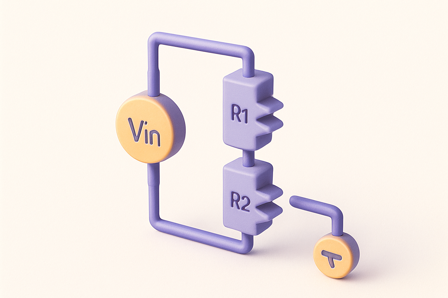
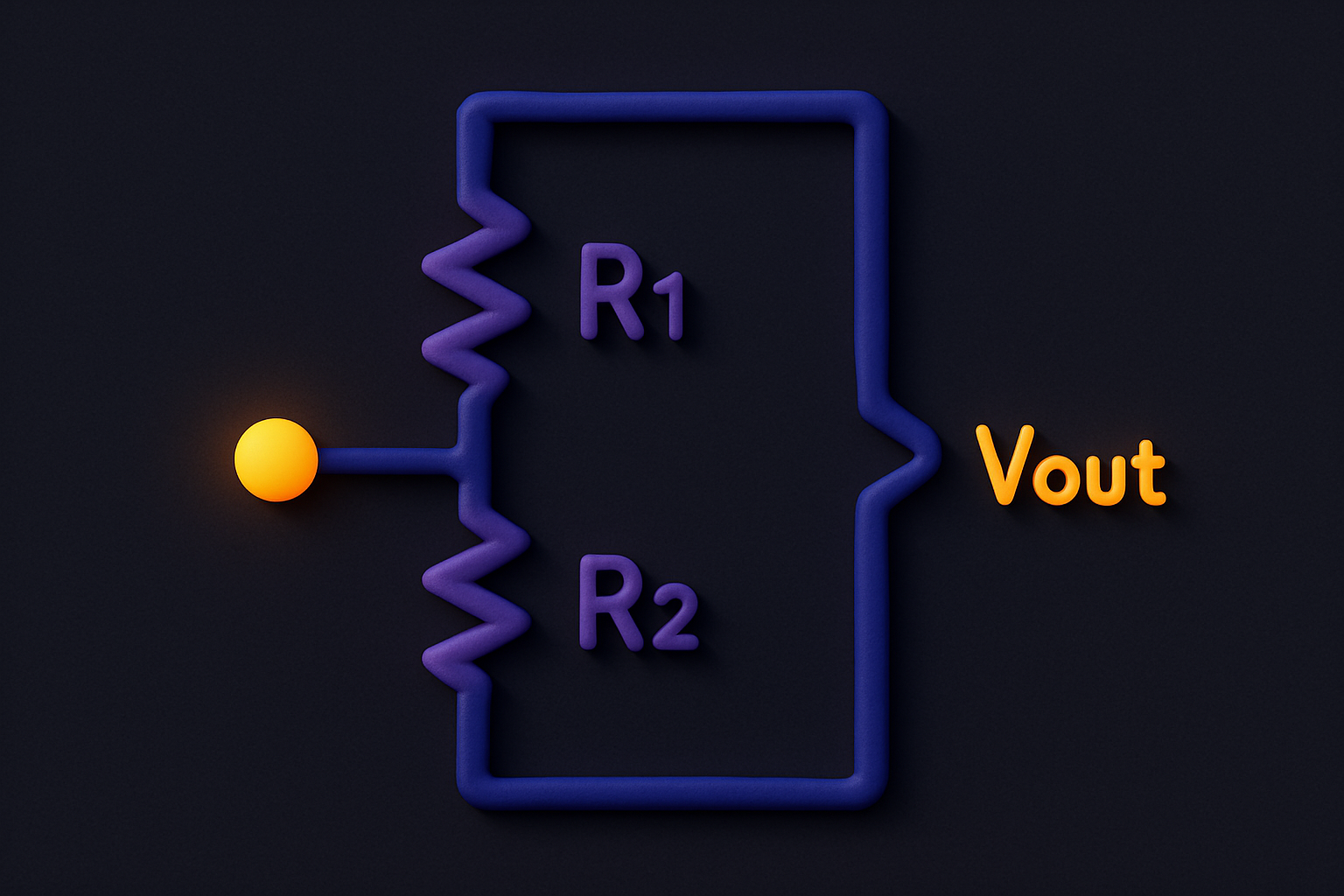
The Voltage Divider Calculator computes the output voltage of a two-resistor voltage divider circuit, or finds the required R2 resistor value to achieve a desired output voltage. A voltage divider is one of the most fundamental circuits in electronics, used to reduce voltage, create reference voltages, and interface between components with different voltage levels. The calculator shows the divider ratio, current flow through the resistors, and power dissipation in each resistor — important for selecting appropriate component ratings.
Why Use Our Voltage Divider Calculator?
- Two modes: calculate Vout or find required R2
- Shows current flow and power dissipation per resistor
- Displays divider ratio for quick reference
- Essential for circuit design and voltage level conversion
Common Use Cases
Level Shifting
Convert 5V logic signals to 3.3V for microcontroller interfacing.
Sensor Reading
Scale sensor output voltage to match ADC input range.
Reference Voltage
Create stable reference voltages from a supply rail.
Battery Monitoring
Scale battery voltage down for measurement by a microcontroller.
Technical Guide
The voltage divider equation: Vout = Vin × R2 / (R1 + R2). Rearranged to find R2: R2 = R1 × Vout / (Vin − Vout). Current through the divider: I = Vin / (R1 + R2). Power dissipation: P_R1 = I² × R1, P_R2 = I² × R2. The divider ratio = R2 / (R1 + R2). Important considerations: the voltage divider equation assumes no load (or negligible load current). When a load is connected, it appears in parallel with R2, changing the effective R2 and reducing the output voltage. For loaded dividers, use R values much smaller than the load impedance (rule of thumb: 10× or more).
Tips & Best Practices
- 1Use resistor values much smaller than the load impedance to minimize loading effects
- 2Higher resistance values reduce power consumption but increase noise sensitivity
- 3Match resistor tolerances for precision applications
- 4Consider temperature coefficients for precision voltage references
Related Tools


Ohm's Law Calculator
Calculate voltage, current, resistance, or power using Ohm's Law and the power equation.


Resistor Color Code Calculator
Decode resistor values from color bands with visual selector for 4-band and 5-band resistors.


Power Calculator (Electrical)
Calculate electrical power, voltage, current, or resistance using power equations.


Percentage Calculator
Calculate percentages, percentage change, and what percent one number is of another.


Fraction Calculator
Add, subtract, multiply, and divide fractions with automatic simplification.


Scientific Calculator
Full-featured scientific calculator with trigonometry, logarithms, factorials, and more.
Frequently Asked Questions
QWhat is a voltage divider?
QCan a voltage divider increase voltage?
QWhat happens when I connect a load?
QCan I use a voltage divider for power applications?
QHow do I choose R1 and R2 values?
About Voltage Divider Calculator
Voltage Divider Calculator is a free online tool from FreeToolkit.ai. All processing happens directly in your browser — your data never leaves your device. No registration required. No ads. Just fast, reliable tools.